
|
In reviewing my web hits I discovered that this article is the single most hit on part of my website. There is no doubt that the SE8C is the most complicated piece of equipment that Digitrax has. If you are looking for some help or have specific questions regarding wiring, programming, scripts, or anything else please E-mail me. Our group has one of these working and in the not to distant future there will be two. I will write an article on how I wired in mine when I am done(Spring 2009)
Email me! |
|
This page outlines and does what I can to explain how I built an interface board to increase the output power of the Digitax SE8C. I have done what I can to try to use as common of parts as I possibly could. I also managed to keep the suppliers to a minimum(2). Please understand that I am not an engineer but a hobbiest that with the help of an electical engineer we designed and built this. I have not done a ton of math on any of the components. I believe the components to be accurate. Bottom line is that you are building this at your own risk. It works for me and I am doing what I can to convey this to you. All pictures in this document are thumbnails of larger pictures. Just click on the pictures and a larger picture will open in a new page. |
|
|
|
|
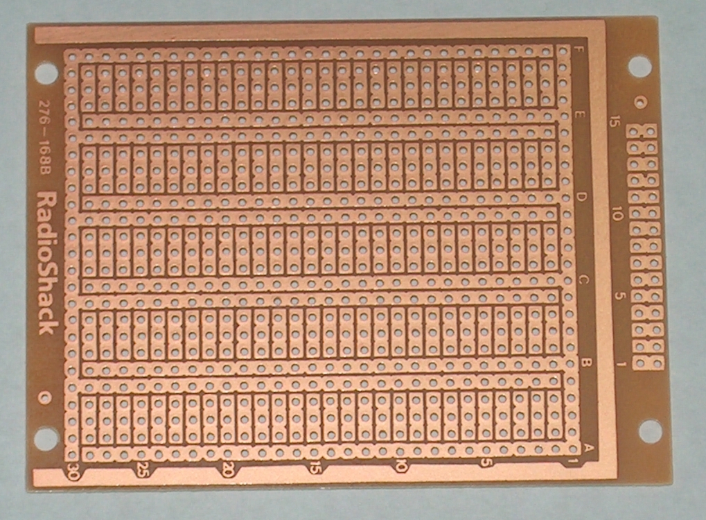
The board to the left is a Radio Shack board that is readily available at this writing.(still available at www.radioshack.com as of October 2010) It is Radio Shack part number 276-168. This is the board that I used to build this project on. I looked into a ready made board but unless I am willing to buy a couple thousand it is cost prohibitive. This project is really quite straight forward so I do not believe it is worth it.
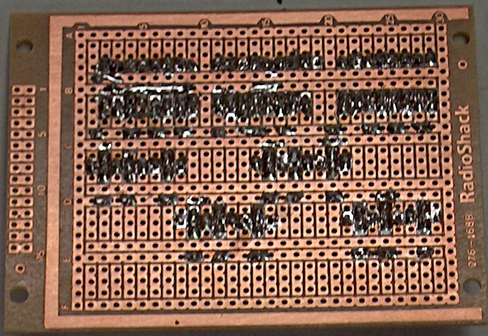
To the right is the copper side of the board as you can see it is a very vesatile board. We will be taking advantage of almost all the busses. Now lets start the project. I like to clean the board with clean Scotch brite. You never know how long the board has been on the Radio Shack shelf. I know that in the old days we used steel wool, I don't like to use steel wool. I believe that it leaves a steel residual on the board. I don't use any kind of liquid on the board. |
|
 |
|
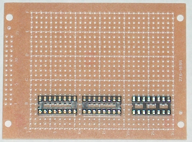
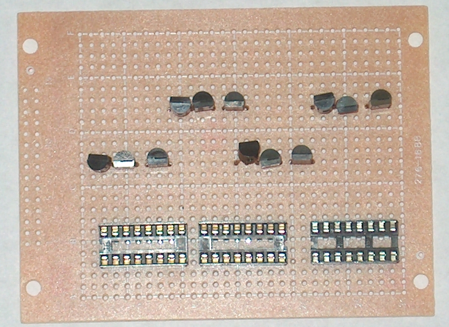
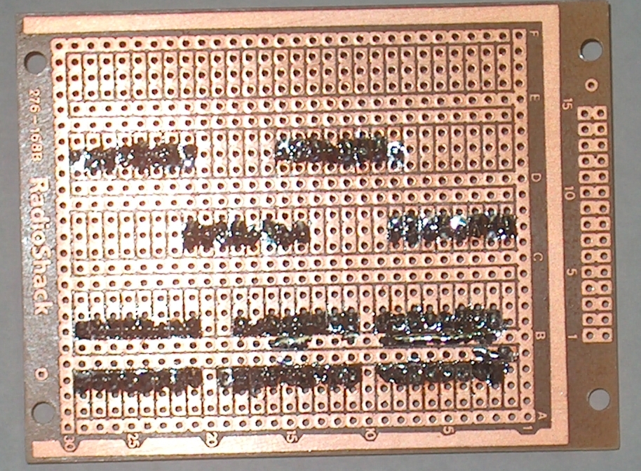
I start with the IC sockets in the picture on the left you can see how I lay them out on the board. These are 16 pin DIP sockets from Digikey. There will be a parts list at the end of this article. To the right is a backside view. |
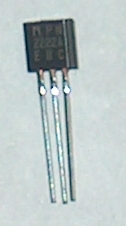 Above is a 2N2222 Transistor from left to right is the emmitter, base, collector. |
|
|
|
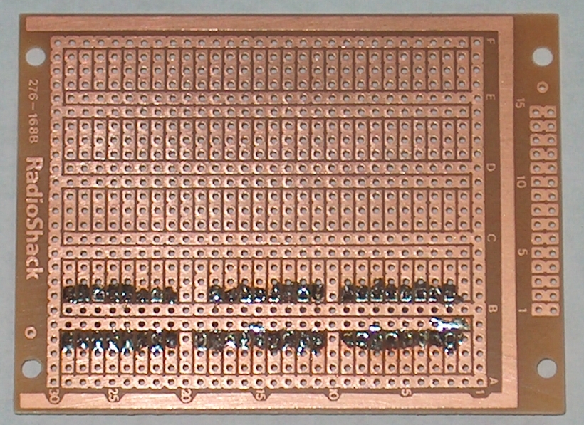
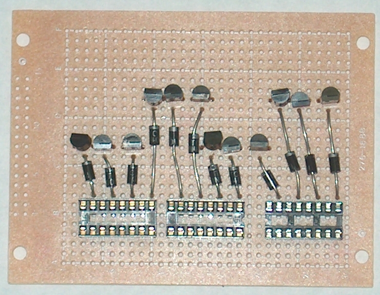
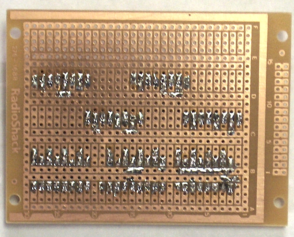
Here is the layout of the transistors. Notice how the emitters of a couple of them share a soldier spot. This makes it easier put the diodes in later. |
|
|
|
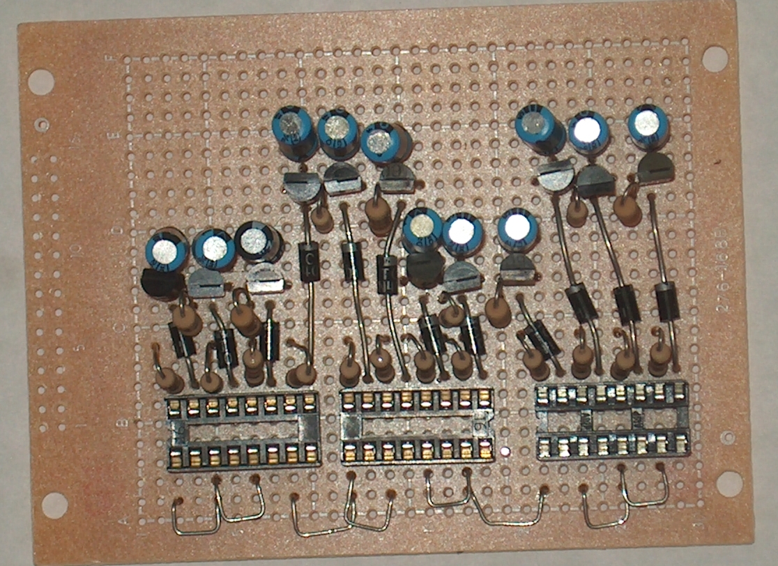
Next the diodes are inserted. Notice the direction that the band is pointing. |
|
|
|
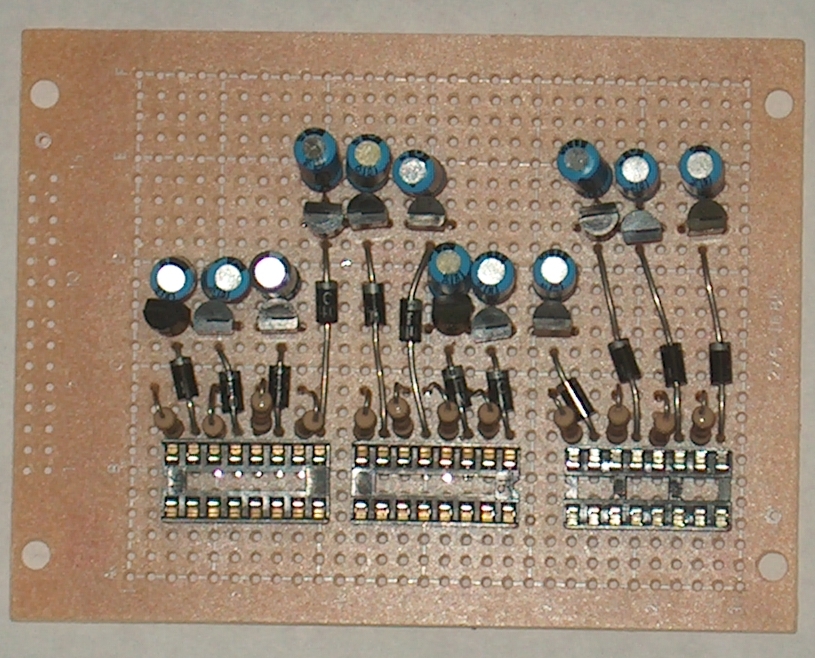
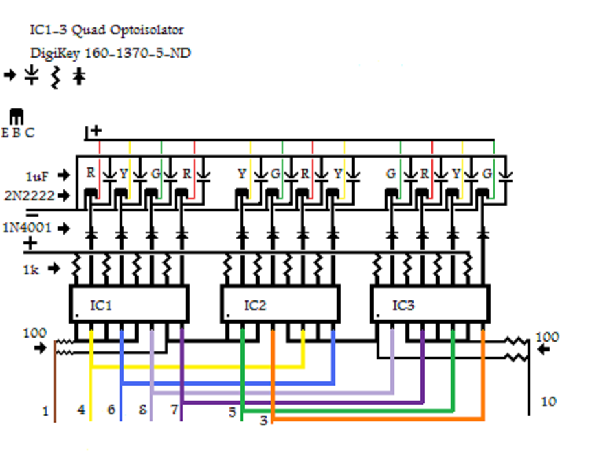
Next I install the 1K resistors and capacitors. The resistor goes to the upper even side of the 16 pin sockects and the other side goes to the positive buss. The positive side of the capacitor goes to the base of the transistors the negative goes to the negative buss. |
|
|
|
It this point there is a choice to make. If you notice I put resistors to the emitters of the transistors. Since these are NPN transistors the other side of the resistor goes to the negative buss. You can also just hook a jumper from the negative buss to the Emitter of the transistor and put the adjusting resistor on the collector of the transistor. Since I don't know which voltage you are using I cannot recommend the resistor for you to use. |
|
|
|
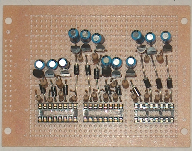
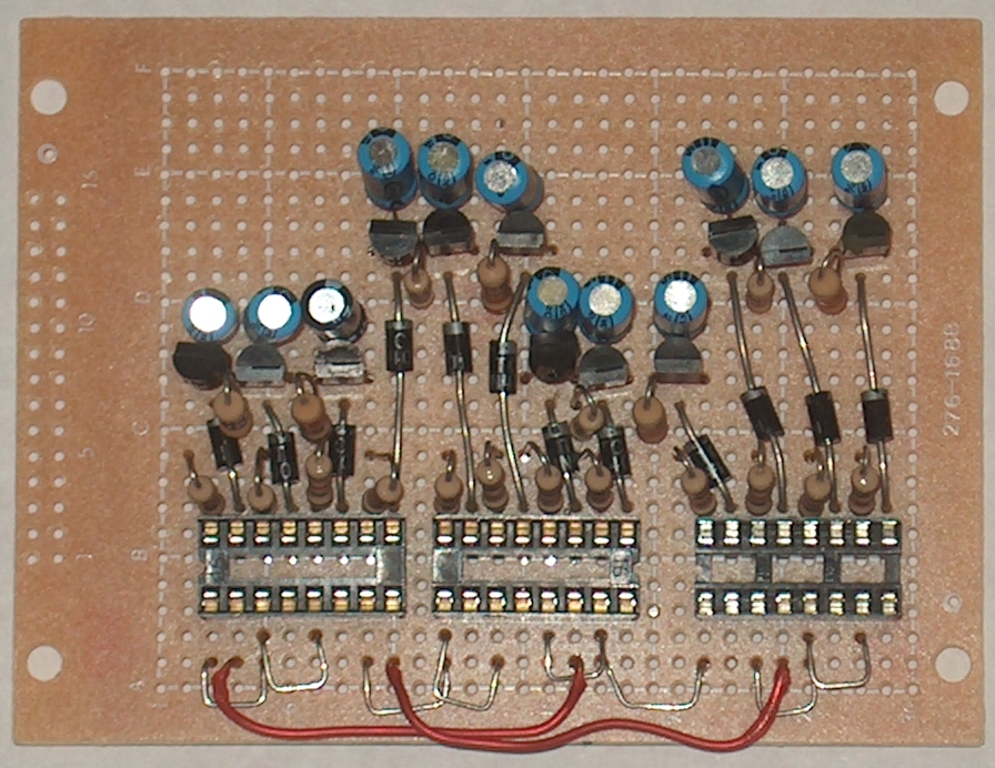
Now we start istalling the jumpers. The left side is for the commons. The right side is the start of the red lights. |
|
|
|
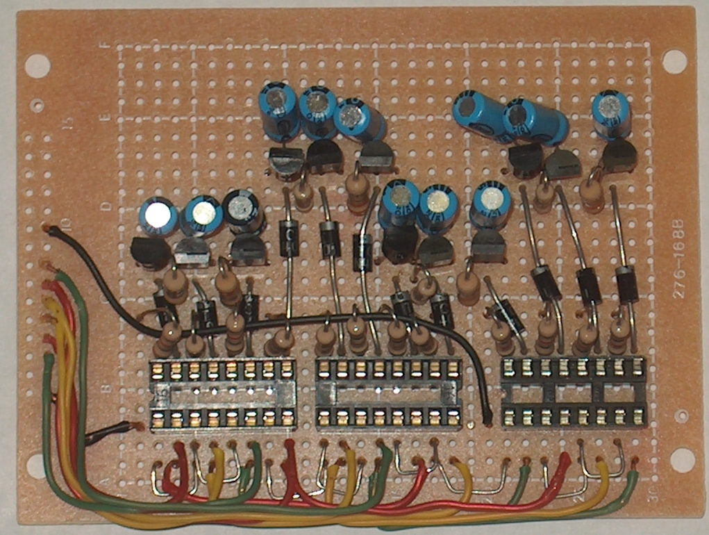
The left picture shows the completion of the jumpers. Please note that I got the green wires in this picture backward. The wires in the diagram are correct. The left picture shows the header installed and the common resistors installed to each end of the matrix. |
|
|
|
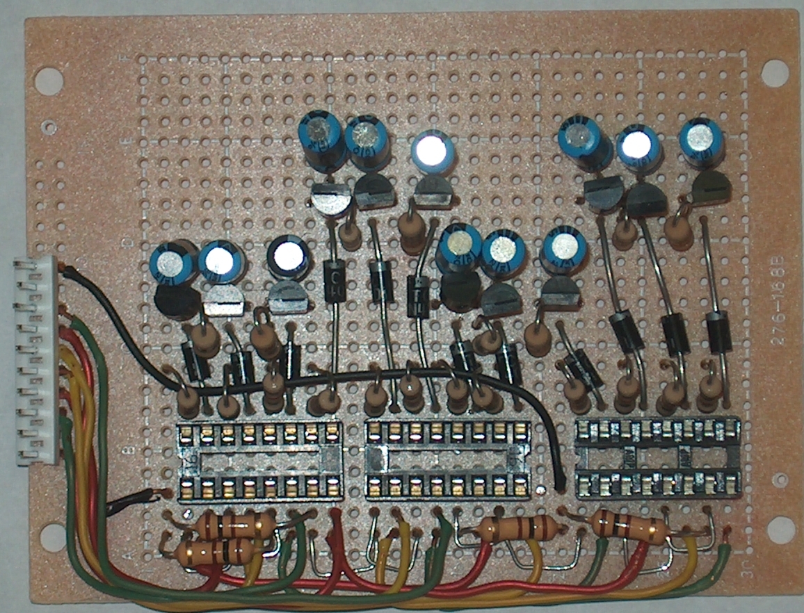
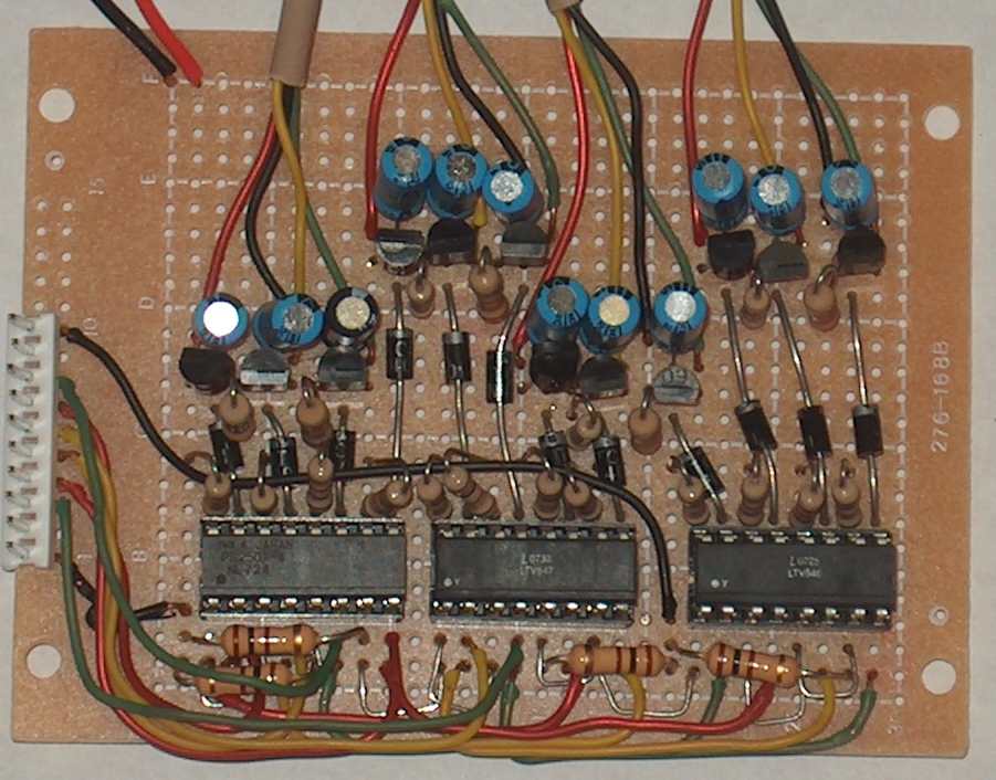
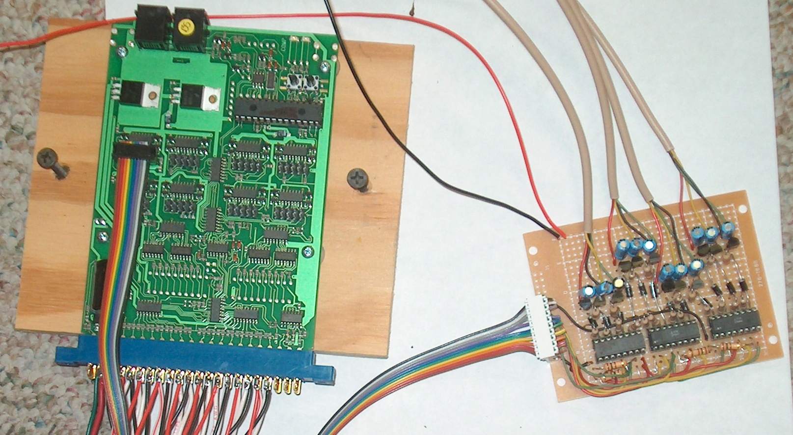
The picture on the left shows the color output of the lights. I used phone wire to connect to the lights. The lights are left to right as you look at it.(SW257-258, SW259-260,SW261-262,SW263-264) In the upper left are the power in wires. The black wire is negative and the red wire is positive. On the right it shows the connection to the SE8c. Note the position of the brown wire. It keys the direction left to right. Reverse one or the other and it will reverse outputs of the lights. |
| 16 pin DIP Socket | AE8916-ND | ||
| 4 Channel Optoisolator | 160-1364-5-ND | ||
| 100 ohm resistor | 100H-ND | ||
| NPN Tranistor | P2N2222AGOS-ND | ||
| 1K Resistor | 1.0KH-ND | ||
| Diodes | 1N4001-NDTPMSCT-ND | ||
| Capacitor 1uF | P5174-ND | ||
| IDC Connectors | (still Digikey) | ||
| 10 Pin Header | A1915-ND | ||
| 10 Pin IDC Connector | A30802-ND | ||
| 10 Pin Strain Relief Cover | A19278 | ||
| T-handle tool For IDC connecor | A9982-ND |
|
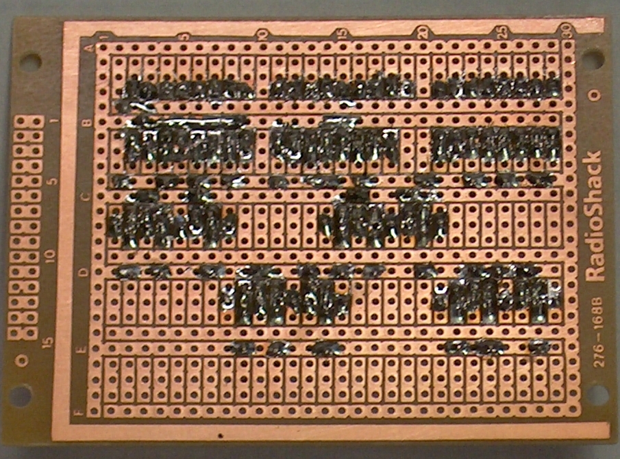
This is how I build the interface boards. Please understand that this is just an concept of what can be done. These outputs can be hooked up to lights, relays, ect. Do not let what I put here limit your imagination of what can be done with these boards. As a building note, the biggest challenge I had building the board was preventing soldier bridges. with the chips out there should be no continuity between the negative and positive busses. also the only place that should have continuity is between resistors. the rest must be open. I spend more time checking for soldier bridges than anything else. I also use the scripts in the JMRI software to control the lights. Soon I will put them on another link for examples of operation scripts. Most Importantly. If I made a mistake in here, I'm Sorry. Please E-mail me at the link on the main page and I will be glad to talk. |